Central Projection
Centre of projection S = (a, b, c, 1),
for c ![]() 0, ( or b
0, ( or b  0)
is a real point in the space
 ![]() ,
,
not located in the image plane - p = xy ( or n = xz ) .
View of an arbitrary point A in the space ![]() ,
A
,
A ![]() S is the point AS in the image plane,
S is the point AS in the image plane,
which is the intersection point of the projecting line sA = AS passing through the point A
and the centre of projection S with the image plane
AS = sA Ç p ( or AS = sA Ç n )
Distance of the centre of projection to the image plane is d = | Sp | = c ( or d = | Sn | = b ) .Matrix of the central projection to the ground image plane p = xy
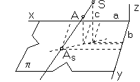

y´ = cy - bz
z´ = 0
h´ = -z + c
AS = A . PSp =
![]()
Matrix of the central projection to the frontal image plane n = xz
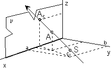
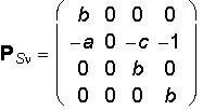
y´ = 0
z´ = -cy + bz
h´ = -y + b
AS = A . PSn =
![]()
Centre of projection S has no view.
Linear perspective
Centre of projection S = (0, 0, -d, 1), distance d = 30cm is the distance of the eye to the image plane.
Matrix of the linear perspective to the ground image plane p = xy

Stereoscopic projection with two centres
Centres of projection 1S = (a, b, -d, 1), 2S = (-a, b, -d, 1),
distance of the eye to the image plane d = 30cm,
distance of centres |1S 2S | = 2b = 6,5cm is the average distance of eyes


Parallel Projection
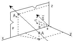
Direction of projection s - a pencil of lines in the space ![]() in the same direction, sharing a commmon ideal point with the line s,
in the same direction, sharing a commmon ideal point with the line s,
determined by the direction vector s = (a, b, c, 0),
c ![]() 0, ( or b
0, ( or b  0 ),
0 ),
intersects image plane p ( or n ) in the real point.
View of an arbitrary point A in the space  is the point
AP Î p ( or AP Î n ),
which is the intersection point of the line sA, A Î sA in the direction s
passing through the point A with the image plane
AP = sA Ç p ( or AP = sA Ç n ) .
Matrix of the parallel projection to the ground image plane p = xy
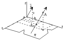
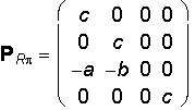
y´ = cy - bz
z´ = 0
h´ = c
AR = A . PRp =
![]()
Matrix of the parallel projection to the frontal image plane n = xz
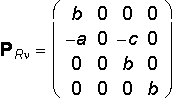
y´ = 0
z´ = -cy + bz
h´ = b
AR = A . PRn =
![]()
Orthographic projection to plane p = xy is represented by the matrix
P 
with two elective angles the azimuth a and the elevation e from the interval <-360°, 360°>.
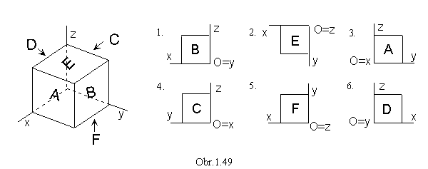
1. a = e = 0° front view (from the front)
2. a = 0°, e = 90° ground view (from the top)
3. a = 90°, e = 0° side view (from the left side)
4. a = -90°, e = 0° side view (from the right side)
5. a = 0°, e e = -90° bottom view (from the bottom)
6. a = 180°, e = 90° back view( from the backward)
7. a = ±45°, e = ±45° isometry (obr. 1.47a)
8. a = 45°, e
 0°, ±45°, ±90°, ±135°, ±180° , ±225° , ±270° , ±315°, ±360°
dimetry (obr. 1.47b)
0°, ±45°, ±90°, ±135°, ±180° , ±225° , ±270° , ±315°, ±360°
dimetry (obr. 1.47b)9. a , e

Monge Method (Multiview Orthographic Drawing)
| GROUND VIEW | FRONT VIEW | SIDE VIEW |
|---|---|---|
 |  |  |
Orthogonal Axonometry
( a, e ![]() 0°, ±90°, ±180°, ±270°, ±360° )
0°, ±90°, ±180°, ±270°, ±360° )
| AXONOMETRIC VIEW | AXON. GROUND VIEW |
|---|---|
 |  |
| AXON. FRONT VIEW | AXON. SIDE VIEW |
|---|---|
 |  |