Problems on Superposition of Space Figures
View of a line, superposition of a line and a point
View of a line is the set of views of all points located on the line.
If a point is located on a line,
views of the point are located on the corresponding views of the line.
A Îa, then A1 Î a1 and A2 Îa2 and A3 Î a3
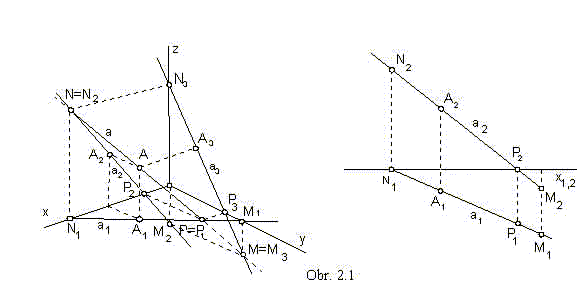
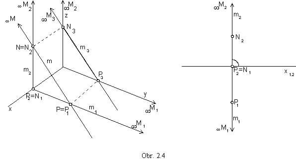
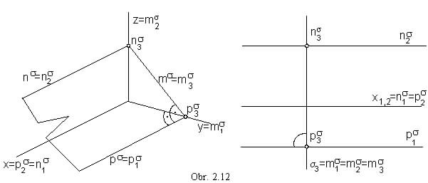
Intersection points of the line and image planes p, n, m are traces of the line, points P, N, M (obr. 2.1).
A line has got an ideal trace, if it is in the direction of the image plane:
p || p
trace in the ground plane ![]() P (obr. 2.2)
P (obr. 2.2)
n || n
trace in frontal plane  N (obr. 2.3)
m || m
trace in the side plane M (obr. 2.4)
Line p is perpendicular to the coordinate axis z .
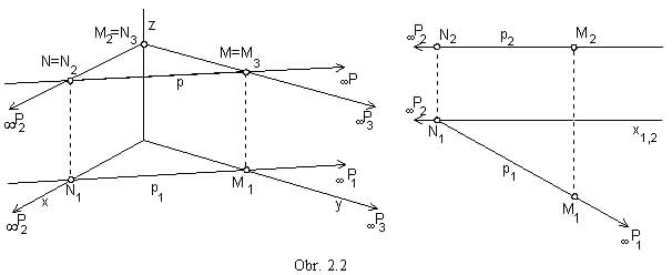
Line n is perpendicular to the coordinate axis y .
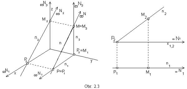
Line m is perpendicular to the coordinate axis x .
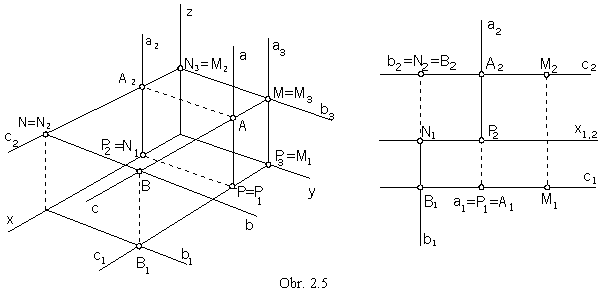
Line perpendicular to the image plane is projected to the point (obr. 2.5).
a ![]() p,
a || z, a Ç p = P
p,
a || z, a Ç p = P
b ![]() n,
b || y, b Ç n = N
n,
b || y, b Ç n = N
c ![]() m,
c || x, c Ç m = m
m,
c || x, c Ç m = m
Superposition of two lines
Parallel lines, which are not in the direction of the projection, are mapped to lines in the same direction in all views.
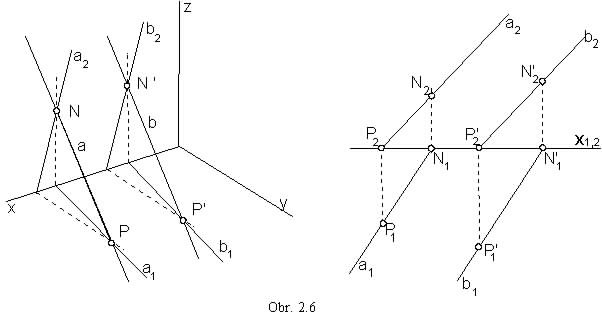
Intersection point R of two intersecting lines a ´ b
mappes into the intersection point of the separate views of lines a , b (obr. 2.7).
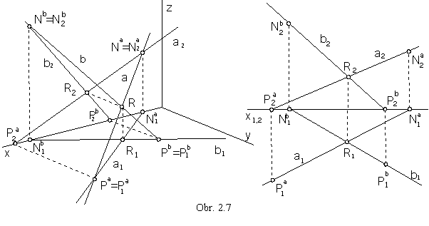
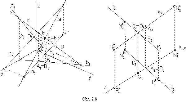
Skew lines have no common point.
Intersection points of the views of skew lines are views of two different points located on different lines (obr. 2.8).
aa Ç ba =
Ea = Fa,
E1 ![]() a1,
F1
a1,
F1 ![]() b1
b1
a1 Ç b1 =
A1 = B1,
A2 ![]() a2,
B2
a2,
B2 ![]() b2
b2
a2 Ç b2 =
C2 = D2,
C1 ![]() a1,
D1
a1,
D1 ![]() b1
b1
Visibility of skew lines can be solved with respect to these points.
Ground view A1 is visible, while ground view B1 is hidden,
point A on the line a has got the greater coordinate z than the point B on the line b.
Front view C2 is visible, while D2 is hidden,
point C on the line a has got the greater coordinate y than the point D on the line b (obr. 2.8).
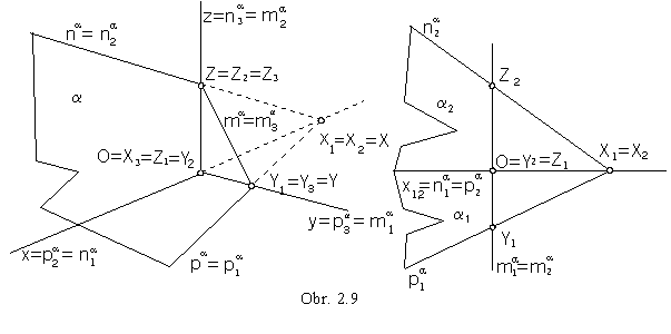
View of a plane
Plane is usually determined by the views of its traces, intersection lines of the plane and image planes.
Intersection points of the plane a and coordinate axes
are intersection points of the plane traces in image planes determined by the concerned axis (obr. 2.9).
a Ç p = pa a Ç n = na a Ç m = ma
a Ç x = pa Ç na = X a Ç y = p a Ç ma = Y a Ç z = na Ç ma = Z
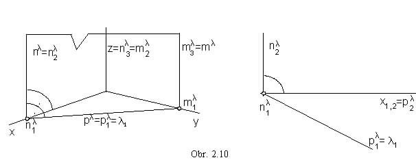
Plane perpendicular to the image plane appears in the edge view, it is projected to a line in the image plane.
l![]() p, l || z (obr. 2.10)
c
p, l || z (obr. 2.10)
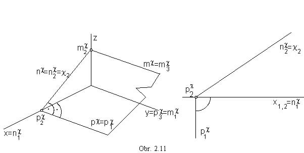
c  n, c || y(obr. 2.11)
s
m, s || x (obr. 2.12)
n, c || y(obr. 2.11)
s
m, s || x (obr. 2.12)
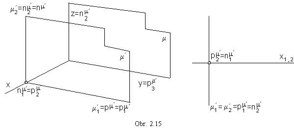
Plane parallel to one image plane is perpendicular to the two other image planes and to their intersection line.
p' || p,
p'![]() n,
p'
n,
p'![]() m,
p'
m,
p'![]() z (obr. 2.13)
z (obr. 2.13)
p' Ç p =
![]() pa
, ground view appears in the true size in the Monge projection method
pa
, ground view appears in the true size in the Monge projection method
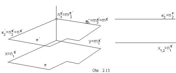
n' || n,
n'![]() p,
n'
p,
n'![]() m,
n'
m,
n'![]() y (obr. 2.14)
y (obr. 2.14)
n' Ç n =
![]() na
, front view appears in the true size in the Monge projection method
na
, front view appears in the true size in the Monge projection method
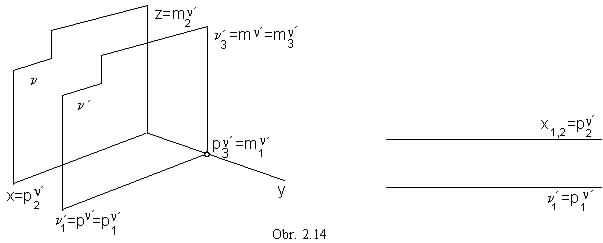
m' || m,
m'![]() p,
m'
p,
m'![]() n,
m'
n,
m'![]() x (obr. 2.15)
x (obr. 2.15)
m' Ç m =
![]() ma
, side view appears in the true size in the Monge projection method
ma
, side view appears in the true size in the Monge projection method
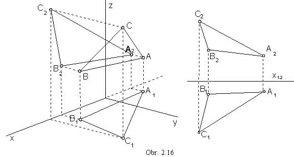
View of the plane is determined also by the view of three different points in the plane (obr. 2.16),
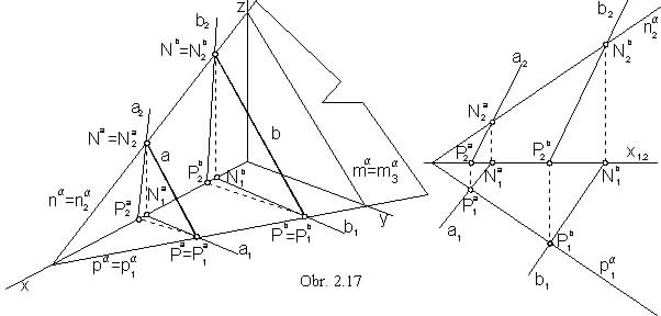
or the views of a pair of lines located in the plane a = ab (a || b, príp. b ´
c ) (obr. 2.17).
Traces of the lines a, b in the plane a determine the plane traces
pa = PaPb,
na = NaNb,
ma = MaMb.
A point and a line located in a plane
A point is located in a plane, when it is located on a line in the plane.
A line is located in a plane, when the line traces are located on the plane traces (obr. 2.18).
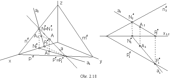
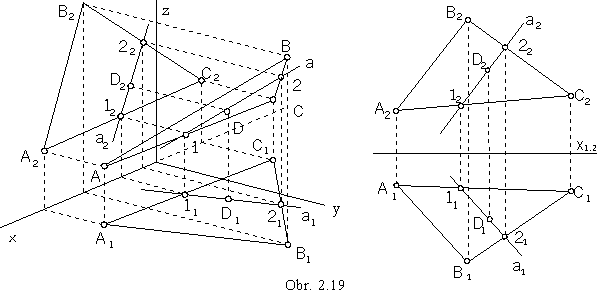
Line a in the plane a intersects all other lines in the plane, in real or ideal points (obr. 2.19).
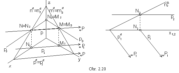
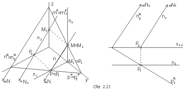
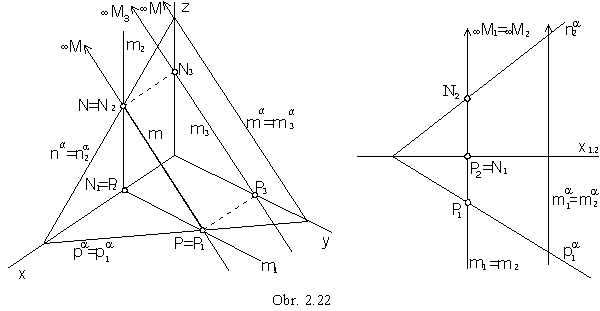
Principal lines in the plane form three frames of lines in a special direction:
p || p, pa Ì p Ist frame, horizontal lines (obr. 2.20)
n || n, na Ì n IInd frame, frontal lines (obr. 2.21)
m || m, ma Ì m IIIrd frame, profile lines (obr. 2.22).
1s![]() pa (and horizontal lines p)
Ist frame (obr. 2.23)
pa (and horizontal lines p)
Ist frame (obr. 2.23)
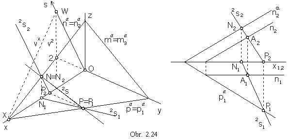
2s![]() na (and frontal lines n)
IInd frame (obr. 2.24)
na (and frontal lines n)
IInd frame (obr. 2.24)
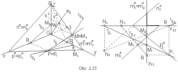
3s![]() ma (and profile lines m)
IIIrd frame (obr. 2.25).
ma (and profile lines m)
IIIrd frame (obr. 2.25).
Monge projection method:
Line 1s1 is mapped to the line perpendicular to the trace p1a
(view of the right angle with one arm pa in p, the other arm
1s is not perpendicular to the plane p).
Front view 1s2 can be determined by traces located on the plane traces (obr. 2.23).
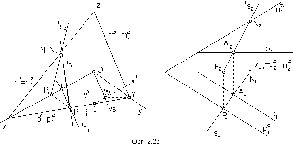
1 Î v1
OY, v1 || x
Y Î vY
z.
Ortocentre W = v1 Ç vY
is the common intersection point of all three altitudes, therefore s = OW ![]() 1Y = pa.
1Y = pa.
Axonometric ground view of the slope line of the Ist frame is in the direction s, 1s1 || s,
axonometric front view 1s2 can be determined by the front views of the line 1s Ì a traces on the plane traces,
and axonometric view 1s = PN is also determined by two points.
Similarly the axonometric front view 2s2 (side view 3s3)
of the slope line of the IInd (IIIrd) frame
can be determined from the triangle O2X (O3Z),
and other views - 2s1, 2s (obr. 2.24)
(3s1, 3s2, 3s (obr. 2.25) ),
can be constructed from the views of line traces.
In the Monge projection method, the front view 2s2 is perpendicular to the trace n2a,
related views of the slope line of the IIIrd frame can be constructed from the third side view,
which is perpendicular to the side view of the plane trace in the side image plane a.
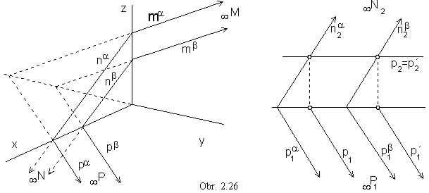
A superposition of two planes
Let two parallel planes a || b be given.
To any line located in one of the planes there exists a parallel line located in the other plane.
Line pa (na,
ma) not intersecting the plane b,
has got no real intersection point with any line in the plane.
Lines pa, pb
are located in the same image plane p (na,
nb Ì n and ma,
mb Ì m) and must be in the same direction.
Traces of parallel planes a || b are in the same direction (they are parallel)
- pa || pb,
na || nb,
ma || mb (obr. 2.26).
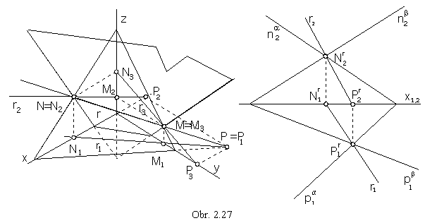
Planes share the same ideal line on which ideal intersection points of their traces are located.
Intersecting planes have a common real intersection line - pierce line r determined by traces,
which are intersection points of plane traces.
Views pa and
pb are located in p and they intersect in the real point
Pr - trace of the pierce line r in the ground image plane
pa Ç pb = P r,
and similarly na Ç nb = N r,
ma Ç mb = M r.
All three points are located on the pierce line, r = P rN r, M r Î r (obr. 2.27).
Superposition of a line and a plane
Let a plane and a line parallel to the plane be given.
There exists a line located in the plane and parallel to the given line.
Let a plane and a line intersecting the plane be given.
There exists a line located in the plane and intersecting the given line in the point,
which is the intersection point of the given line and the given plane .
Let one of the line a views coincides to the view of the line k located in the given plane a.
This line is called cover line.
Other view of the line k can be determined by the intersection points of the line k
and other two lines located in the plane a - traces, or any two parallel or intersecting lines h, l.
a = pa na : a1 = k1 a2 Ç k2 = R2 (aa Ç ka = Ra) R1 Î a1 a Ç a = R (obr. 2.28a,b)
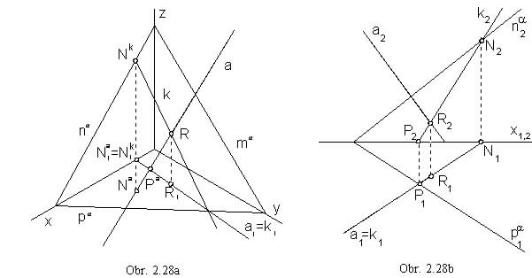
Described construction method for the intersection point of a line and a plane is the cover line method.
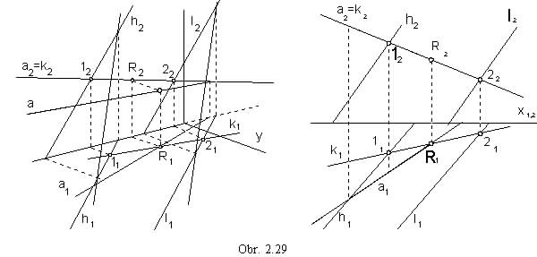
a = h || l: a2 = k2 a1 Ç k1 = R1 R2 Î a2 a Ç a = R (obr. 2.29)
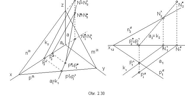
Line a parallel to the plane a is parallel to the cover line k.
a = pa na:
a2 = k2
a1 || k1
a || a
a1 = k1
a1 || k1
a || a (obr. 2.30)
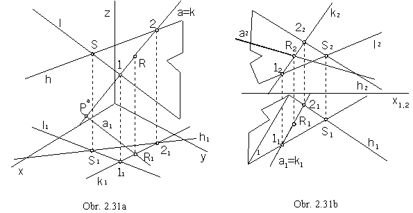
a = h ´ l :
aa = ka
a1 Ç k1 = R1
Ra Î aa
(obr. 2.31a)
a1 = k1
a2 Ç k2 = R2
R1 Î a1
a Ç a = R
(obr. 2.31b)
Line intersecting two skew lines
Line intersecting two skew lines is any line, determined by points located on the given skew lines.
There exist infinitely many lines of this type.
A unique solution can be determined attaching an additional condition.
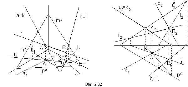
Line r intersecting two skew lines and located in the given plane a
Line r is determined by intersection points of the two skew lines and the given plane a.
a / b, a Ça = A, a Ç b = B, r = AB - in the plane a (obr. 2.32)
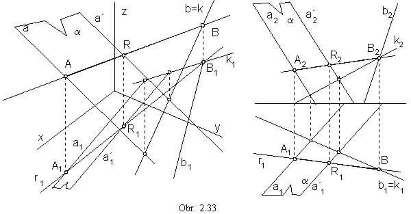
Line intersecting two skew lines located in the given point R
Line r is determined, in addition to the point R, by the intersection point of one of the given skew lines and the plane located in the point R and parallel to the other skew line.
a / b, Ra = a, a Ç b = B, r = RB, r Ç a = A (obr. 2.33)
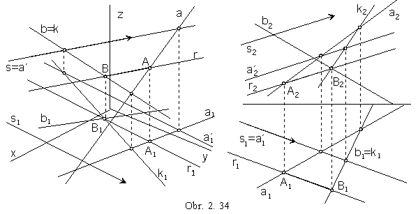
Line intersecting two skew lines in the given direction s
Line r is determined, in addition to its direction (which must be not parallel to any of the skew lines), by the intersection point of one of the given skew lines and the plane parallel to the given direction and passing through the other skew line.
a / b, s: a Ì a || s, a Ç b = B, B Î r || s, r Ç a = A (obr. 2.34)
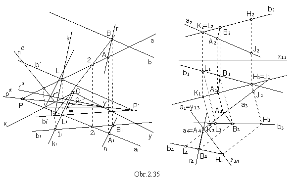
Axis of skew lines
Line r perpendicular to both skew lines and intersecting them in real points is the axis of skew lines.
This line is perpendicular to the plane parallel to the both skew lines.
a / b, a || a, a || b,
k![]() a,
r || k (obr. 2.35)
a,
r || k (obr. 2.35)
a = ab', a Ç b' = L, b' || b plane a parallel to both skew lines a, b
a Ç r = ra,
L Î k, ka
line k perpendicular to the plane a
determined by
k ra,
k1 || OW
axonometric view and axonometric ground view
b = ak plane b parallel to the direction k of the axis of skew lines
b Ç b = B, B Î r || k, r Ç a = A axis of skew lines r, ç AB ç is the distance of skew lines
Problem can be solved in the Monge projection method using additional third and fourth views,
while the third side image plane is passing through the line a perpendicularly to the ground image plane,
and the fourth side plane is perpendicular to the ground image plane and the line a.
The fourth view of the line segment AB appears in the true size, and it determines the distance of the skew lines.