Lines (planes) having a common ideal point (ideal line) will be denoted as parallel lines (planes).
Metric Problems
To reconstruct figures from their views, or to find a view of the figure determined by its dimensions and
metric properties of its elements, are tasks realised by means of basic constructions covering the basic problems on metric properties.
There can be distingueshed two basic types of metric problems:
Metric properties are related to the real elements of the space ![]() E3,
therefore the term "parallelism" of the Euclidean geometry will be used in the related problems.
E3,
therefore the term "parallelism" of the Euclidean geometry will be used in the related problems.
Lines (planes) having a common ideal point (ideal line) will be denoted as parallel lines (planes).
Size of a line segment - length
Orthographic view of a line segment is a line segment with the length shorter or equal to the length of the original
line segment.
In the parallel (orthogonal) projection, line segments appear in the true size, when located on lines parallel to the image plane.
Size of a line sgment located on line in a general position with respect to the image plane can be determined
by means of several constructions.
I. Lowering of the projecting plane
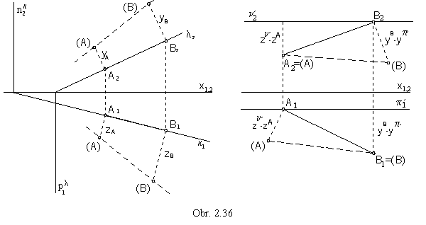
Line segment (as a part of a line) is projected in the projecting plane perpendicular to the image plane (Fig. 2.36),
ABÌ k, k ^ p, AB Ì l, l ^ n.
Revolution of the projecting plane by 90° about the intersection line with the image plane (trace of the plane)
into the image plane is the lowering of the projecting plane.
Projecting lines of points A and B are lowered into the lines perpendicular to the edge view of the plane
and the lowered points (A) and (B ) are located on them, in the distances equal to their distances from the image plane,
coordinates zA , zB in lowering to the p,
and yA , yB in lowering to the n.
Invariant line of the lowering, the trace of the plane, is a part of both the lowered plane and the plane to which we lower the given plane.
Lowered figures will be drawn in dash lines and denoted by the names in the brackets.
The true size of a line segment appears in the lowered position, |AB | = | (A)(B) |.
The plane can be lowered also to the planes parallel to the image planes, p´ or n´.
The distance to which points will be lowered is in this case equal to the difference of the due coordinates of the
point and the planep´
or n´.
II. Revolution of the line segment to the position parallel to the image plane
The length of a line segment not appearing in the true size can be determined also by revolving the line
segment about the axis perpendicular to one of the projection planes to the position parallel
to the other projection plane (Fig. 2.37).
Axis of revolution is passing through one of the line segment end points, which remains invariant in the revolution.
All other points of the line segment are revolving on circles (with centres at the axis of revolution)
in planes perpendicular to the axis of revolution to the plane parallel to one of the image planes.
They create a part of the conical surface of revolution, two line segments on this surface patch,
0A 0B and
0A 0B´ ,
or 0A´ 0B are parallel to the image plane and appear in the true size.
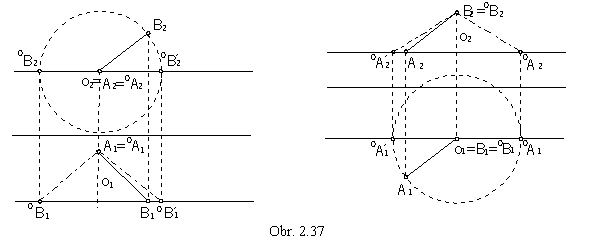
| AB | = | 0A1 0B1 | = | 0A1 0B1´ |, or | AB | = | 0A2 0B2 | = | 0A2´ 0B2 |
III. Transformation of the image plane - new, additional sideviews
 Another solution how to find a line segment length is to add a new image plane,
parallel to the give line segment, in order to get new true size view of the line segment.
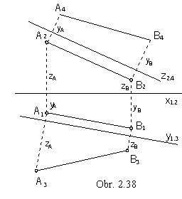
The additional side image plane ( perpendicular to p ) intersects the horizontal plane
in the axis y1,3,
while the first and the third views will be related in the direction perpendicular to this line (Fig. 2.38).
Distance of the third view of the point from the axis y1,3 equals to the distance of the second view
of the point from the axis x1,2, it is the distance of the point from the horizontal plane, its coordinate z.
Similarly the fourth image plane (perpendicular to n) intersects the frontal plane
in the axis z2,4.
The second and the fourth views of points will be related in the direction perpendicular to this axis,
distance of the fourth view of the point from the axis z2,4 equals to the distance of the first view
of the point from the axis x1,2, it is the distance of the point from the frontal plane, its coordinate y.
| AB | = | A3 B3 | = | A4 B4 |.
A similar problem is to draw views of a line segment given in the true size and located on a line.
In the orthogonal axonometry, the length of line segments on the coordinate axes x, y, z
projected into the axonometric image plane is scaled, does not appear in the true size.
Coordinates of points can be not used in their true size.
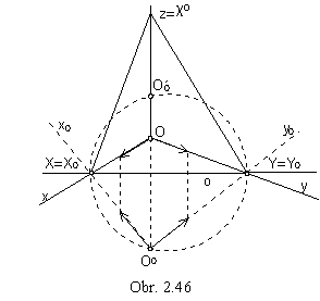
Lowering of the projecting planes of the separate coordinate axis to the axonometric image plane
r lowered positions (x), (y) and (z) are determined, on which coordinates appear in the true size.
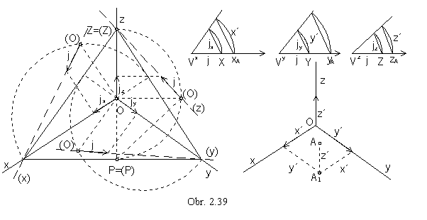
Triangle ZPO (obr. 2.39) is located in the projecting plane c of the axis z.
It is a rightangled triangle, PO ^ OZ
( POÌ p, OZ = z ) and its hypotenuse
PZ located in the axonometric image plane is invariant in lowering.
Point (O) is the vertex of the right angle above the hypotenuse PZ, it is located on the circle of Thales with the diameter PZ
and on the lowered projecting line perpendicular to PZ.
Unit line segment j on the lowered axis (z) = (O)(Z) is mapped to the line segment
jz Ì z.
Similarly the views of the unit line segments on the coordinate axes x and y can be determined.
Scaling ratios on separate coordinate axes can be represented by reduction angles (obr. 2.39).
They can be constructed in the arbitrarily chosen vertices VX, VY, VZ,
which are centres of circular arcs of the radii equal to the unit line segment size
j = | V x X | = | V y Y | = | V z Z |.
Chords of these circular arcs have the size of the scaled views jx , jy , jz of the unit line segment on axonometric views of the corresponding coordinate axes
x, y, z.
Coordinates of any point A = [ xA, yA, zA] can be
scaled in the corresponding reduction angle and then used directly on the axonometric views of the coordinate axes.
In the trimetry the angles are different, in the dimetry two of them are equal and in the isometry all three angles are equal.
Size of the angle
If the angle formed by two geometric figures is a right angle, we speak about perpendicularity of the figures.
Right angle can be mapped as a right angle iff it is in a special position to the image plane.
Slope lines of the plane are mapped in one of their related views to lines perpendicular to the view of plane trace
(and views of principal lines).
Line is perpendicular to the plane, if it is perpendicular to all lines located in the plane.
It is therefore perpendicular also to the principal lines of the first frame (and plane trace in the ground image plane),
and this right angle appears as a right angle in the ground view.
Line is also perpendicular to the principal lines of the second frame (and plane trace in the frontal image plane),
while this right angle appears as a right angle in the front view (obr. 2. 40).
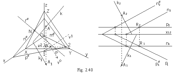
Plane a passing thropugh the given point R and perpendicular to the given line k is determined by the principal lines p and n.
R Î a ^ k, a = (p, n), p ^ k, n ^ k, p Ç n = R
In the orthogonal axonometry, the axonometric ground view k1 of the perpendicular line to the plane,
and therefore to the plane trace pa, can be determined by means of the
triangle 12O orthocentre.
Altitude to the side 12 Ì pa
is OW = v0, A1 Î k1 || v0.
Axonometric view of the line k perpendicular to the plane is mapped to the line perpendicular to the intersection line of the plane and the axonometric
image plane, axonometric trace of the plane ra (obr. 2.40).
Angle of the line (plane) to the image plane is the slope of the line (plane) to the image plane.
Slope of the line can be determined by lowering of the line projecting plane to the related image plane (obr. 2.41).
Lowered line is easily determined by its traces, one of which is always invariant,
it is located in the image plane, to which the projecting plane is lowered.
ú ![]() a p
ú = ú
a p
ú = ú ![]() a1(a) ú =
j
ú
a1(a) ú =
j
ú ![]() a n
ú = ú
a n
ú = ú ![]() a2 (a) ú =
y
a2 (a) ú =
y
Slope of the plane to the ground image plane is determined by the slope line of the first frame,
slope to the frontal image plane by the slope line of the second frame (obr. 2.42).
ú ![]() a p ú = ú
a p ú = ú
![]() 1s p
ú = ú
1s p
ú = ú ![]() 1s1(1s) ú =
j
ú
1s1(1s) ú =
j
ú ![]() a n ú = ú
a n ú = ú
![]() 2s n
ú = ú
2s n
ú = ú ![]() 2s2(2s) ú
= y
2s2(2s) ú
= y

Angle of two lines appears in the true size iff both lines are parallel to the image plane.
Size of the angle of two lines in the general position
can be determined by the revolution of the plane formed by the two lines
to the plane parallel to the image plane, or directly to the image plane.
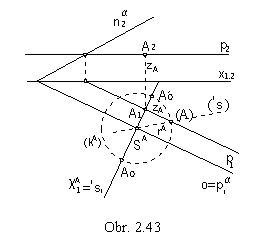
Revolution of the plane :
Revolution of the plane a to the ground image plane
a = (pa na), A Î a
Revolution to the plane a to the plane n´ parallel to the frontal image plane
a = (A, n)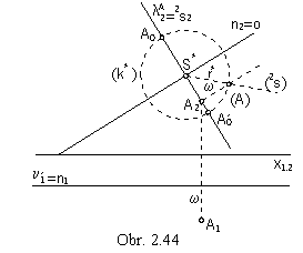
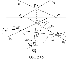
Problem 2.1: Determine the true size of the angle of two intersecting lines a, b (obr. 2.45).
 Solution:
Lines determine plane a = ( a, b).
Line traces P and P´ in the ground image plane are located on the plane trace in the ground image plane,
the axis of revolution of the plane a to the ground image plane, these are line invariant points in the revolution.
Point R revolves in the plane of revolution
cR perpendicular to the axis of revolution, on a circle of revolution
kR
with the centre in the point SR = cRÇo
and radius r=|SRR|.
Lowering the line segment SRR the radius of revolution can be determined.
Angle of lines a0=P0´R0 and b0=P0R0
is the angle of the intersecting lines a and b in the true size.
Eckhardt (Intersection) method
Axonometric view of the figure can be constructed easily from the given two orthographic views, ground view and fronat view (obr. 2.47).
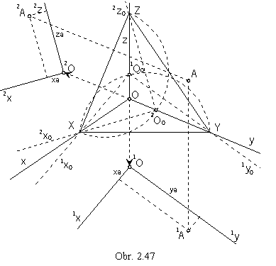 Revolving ground plane p about the line XY to the axonometric image plane,
1O01x01y0 -
revolved coordinate system can be determined.
Revolved ground plane can be translated in the drawing sheet in the direction of the coordinate axis z,
out of the axonometric triangle XYZ to make the drawing readable,
to 1O1x1y,
and the ground view of the point A can be determined
by the coordinates xA , yA.
Similarly, the frontal plane n can be revolved about the line XZ to the axonometric image plane,
and revolved coordinate system 2O02x02z0 can be determined.
Revolved frontal plane can be translated in the direction of the coordinate axis y out of the triangle XYZ to
2O2x2y.
By coordinates xA and zA the front view of the point A can be determined.
Axonometric view of the point A is the intersection point
of line passing through the point 1A and parallel to the coordinate axis z,
and the line passing through the point 2A and parallel to the coordinate axis y.
The presented method is the Intersection, or Eckhardt method and is widely used in constructions of realistic views of different
objects determined by the two orthographic views.
In the skew axonometric projection, the position of orthographic views of figures and the direction of translations
1OO, 2OO
can be determined arbitrarily, with respect to the realism of the skew axonometric view.
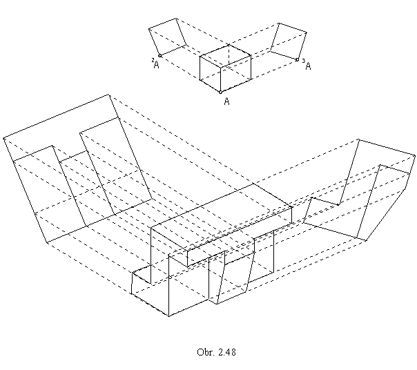
In the Obr. 2.48, the skew axonometric view of a machine part determined by the front view and side view is presented.
Position of the views and the directions of translations are chosen with respect to the realistic view of a cube.
