Monge method
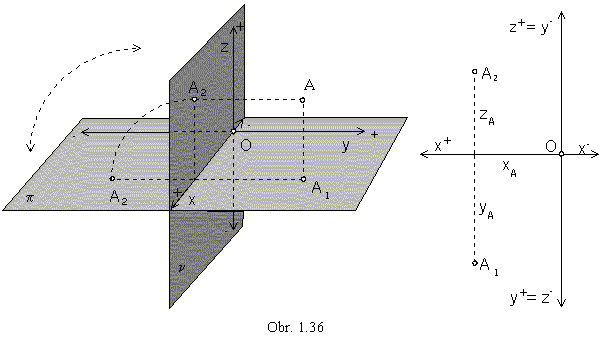
Monge method is an orthographic mapping to the two perpendicular image planes (obr. 1.36)

Any point A in the space ![]() E3 can be attached a pair of related views (A1, A2),
where
E3 can be attached a pair of related views (A1, A2),
where
A1 is the orthographic view in the ground plane p - ground (plan, top) view of the point A
and A2 is the orthographic view in the frontal plane n - front view of the point A.
Additional orthographic views to the additional image planes can be attached,
if necessary for views of more complex and difficult objects.
Choosing new image planes perpendicular to the ground plane and frontal plane,
the third and fourth views can be determined, in the right or the left side (profile) plane.
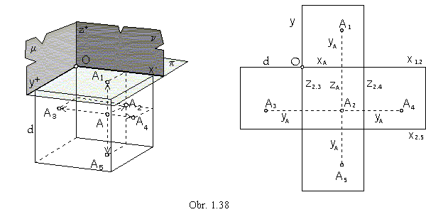
The fifth image plane is parallel to the ground plane and provides the view from the bottom (obr. 1.37).

In the multiview orthographic method, the separate view of the point A= (xA, yA, zA, 1) are determined by the following Cartesian coordinates in the image planes:
A1=[xA, yA] - groung view A2=[xA, zA] - front view
A3=[yA, zA] - left side view A4=[yA+d, zA] - right side view
A5=[xA, yA+d] - bottom view
for the distance d¹0 of the two side image planes, or the groundplane and the fifth image plane.
Distribution of separate views on a technical drawing is in Obr. 1.37 right (European norms),
mapped figures are usually located in the coordinate trihedron Ox+y+z+.
In the American normalisation, mapped figures are located into the coordinate trihedron Ox-y+z-
and distribution of the views on a technical drawing is in the Obr. 1.38 right.

Basic image planes, ground plane p and frontal plane
n,
can be located into one plane revolving one of them to the other one about the common line in the coordinate axis x.
In this way, we get the views relative positions in a one-plane sheet of drawing paper,
pairs of point A related views (A1, A2), while
A1A2![]() x1=x2
(line x is located in both image planes).
x1=x2
(line x is located in both image planes).
Perpendicular image planes p and n divide the space into
four quadrants.
Coordinates of points located in the separate quadrants satisfy the following inequalities:
II. yB< 0, zB> 0 IV. yD> 0, zD< 0.
Related views of the points A, B, C, D are in the Obr. 1.39.

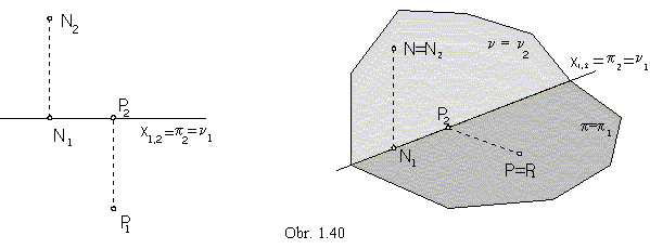
Front view of the ground plane and ground view of the frontal plane are in the reference line x1,2.
Any point in the ground plane, PÎp, has got the front view on the reference line x1,2
(|Pp|=0),
and any point in the frontal plane, NÎn,
has got the ground plane on the reference line x1,2 (|Nn|=0), too (obr. 1.40).
